| Ypsilanti, Michigan Weather | |||||||||
 |
Civilian Weather Observation Program EW0985 |
 |
|||||||
|---|---|---|---|---|---|---|---|---|---|
| By: Jay Nugent - WB8TKL | - Aspirator construction details - | Latest Update: Sept 13th, 2012 | |||||||
| Ypsilanti, Michigan Weather | |||||||||
| |
Civilian Weather Observation Program EW0985 |
|
|||||||
|---|---|---|---|---|---|---|---|---|---|
| By: Jay Nugent - WB8TKL | - Aspirator construction details - | Latest Update: Sept 13th, 2012 | |||||||
|
|

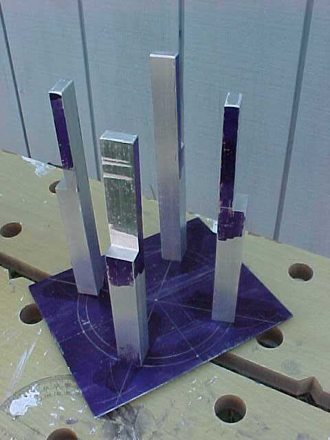
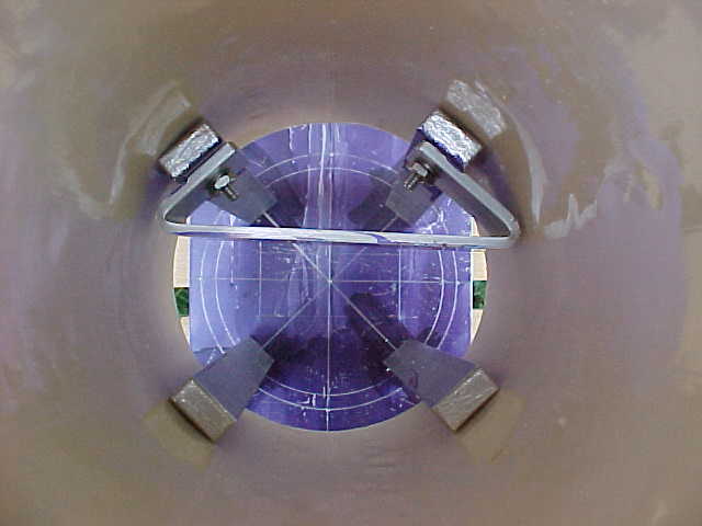 A thin sheet of 1/16" plate is used as the base. On this are mounted 4 posts of 5/8" square aluminum bar that have been milled with a step about 4 inches above the base, leaving roughly 3 inches to support the PVC tube. A single screw comes up through the base into the bottom of each post - allowing them to be rotated for alignment as necessary. These posts will easily slide up inside the 4-inch PVC tube that will be added later.
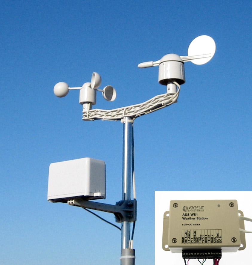
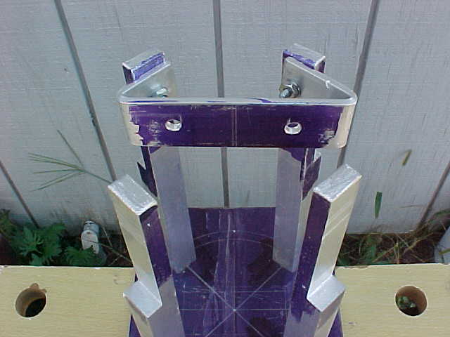
A 1"x1/8" aluminum bar is folded on each end to wrap back and form a 45-degree surface that lines up with each of the rear two posts where they are then attached. This bar is drilled with two holes to mount the ADS-WS1 control module to, holding it in the center of the air stream traveling up through the center of the PVC tube.
This last photo shows how everything lines up when the PVC tubing is placed over the entire apparatus.
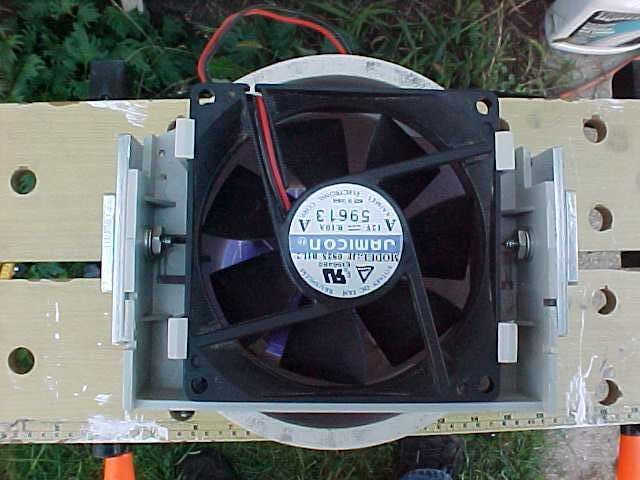
 Luck would have it that I had recently scraped out an old PC and had saved a plastic frame that held the Speaker and a Cooling Fan. Cutting off the portion holding the Speaker and performing a little trimming here and there resulted in a very nice Fan Holder! As replacement fans are needed - simply snap out the old one and snap in the new one - no tools required.
The second photo shows how the Fan Holder is held in place with two strips of 1"x1/8" aluminum bar. A small piece of aluminum bar was just enough to fill some space (rather than use washers) so that the two mouting bars could line up parallel to the sides of the PVC tubing. Some 6-32 screws and washers completed the mount.
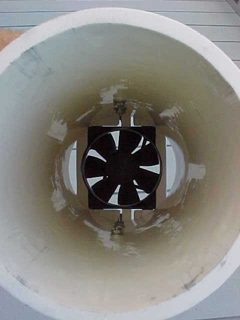
Looking down the PVC tube shows the fan from underneath. You can see that it covers the open end of the PVC tube rather well. But even if the fan stops spinning, air can still move freely past the fans and air gaps.
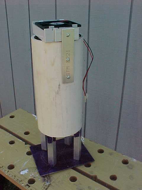
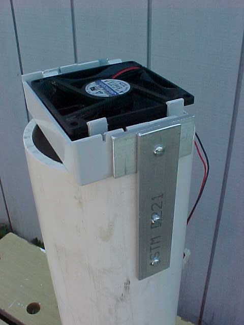
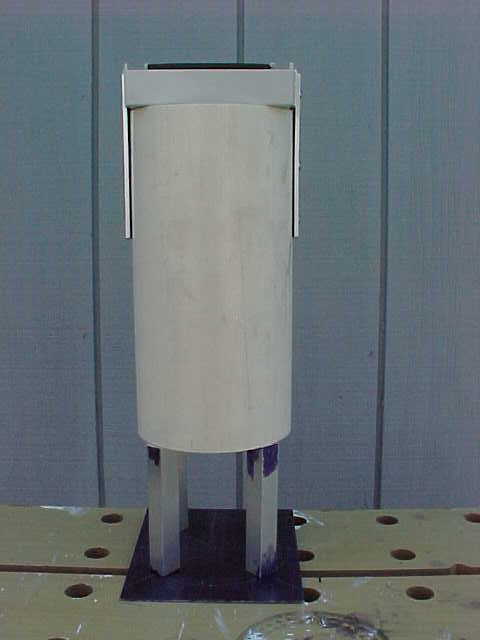 With everything fitted together, this makes for a nice little package! The whole package stands approximately 16 inches tall.
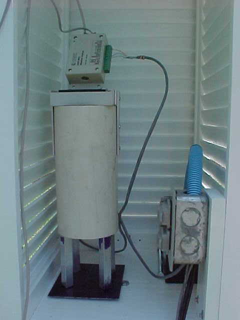
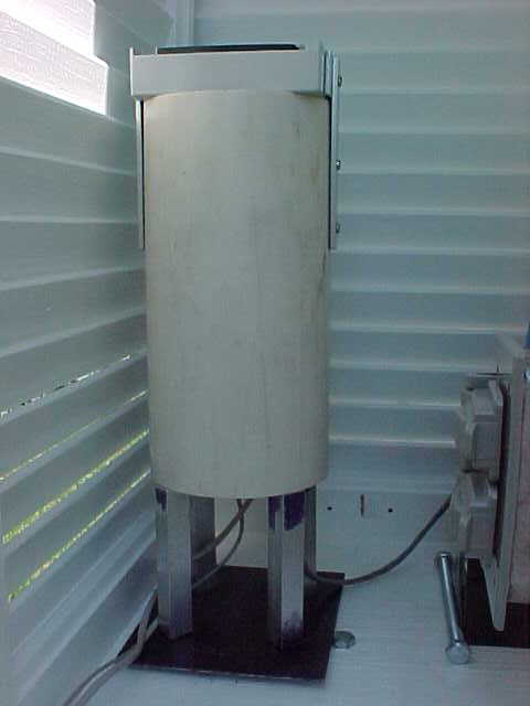
 Here we see the Aspirator placed inside the Gill box. The ADS-WS1 module is resting on top of the fan. This should give some prespective as to the size of each part of the system.
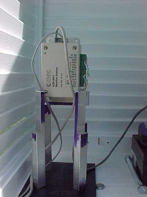
In the second picture we see the ADS-WS1 mounted in position within the Aspirator framework. Wiring is passed down through the *intake*, or bottom end of the device so that the PVC tube can be removed without disturbing the operation of the Weather Station.
Finally, we see the Aspiration system complete and ready for service!


These pages are maintained by:
jjn@nuge.com
Copyright © 2012 John (Jay) Nugent - WB8TKL
All Rights Reserved. All other Copyrights and
Trademarks are property of their respective owners.
